Telemetry Collector
The code for this component is located in the telemetry-collector.
All communications from the vehicle come over the RFD900x module which reports UART back to us. This repository is the software responsible for decoding the message after it is sent over UART and sending it to the correct endpoint on PIT GUI.
Model
The decoding of transmissions is roughly based on the OSI Model. Our implementation is simplified with three layers utilized, the physical layer, data link layer, and network layer. The first two layers are standard protocols that are listed below.
Physical Layer: UART Protocol
Data Link Layer: Byte Stuffing
The data link layer reports the data to the network layer which then reports to the correct endpoint. The graph looks a little like this
     Custom        (Network Layer)
       ^
       |
   Byte Stuffing   (Data Link Layer)
       ^
       |
UART Transmissions (Physical Layer)
Step 1: Data Link Layer
When the UART transmissions are reported to the Data Link Layer the messages are encoded using special bytes. There is a start byte indicating the beginning of a transmission and an end byte for the end of the transmission. Anything between the start and end bytes can be considered data. If the start or end bytes show up in the the data section then they need to be escaped with the escape byte. The escape byte indicates that the next byte is a special character, but it can safely be ignored because it is part of the data. This prevents the transmission from ending early if the stop byte shows up in the data and other situations. Note that if the escape byte shows up in the data then it needs to be escaped too!
Special Bytes |
|
|---|---|
Start Byte |
0xFF |
End Byte |
0x3F |
Escape Byte |
0x2F |
Example
0xFF  | 0x01 | 0x02 | 0x2F | 0x3F | 0x05 | 0x3F
-----------------------------------------------
START | DATA | DATA | ESC  | DATA | DATA | END

Packet: 0x01, 0x02, 0x3F, 0x05
Step 2: Network Layer
The network layer is a custom protocol used for sending telemetry information in a way that is easily verifiable. The protocol is separated into messages and data. The first byte in the transmission is the number of messages in the transmission. For every message there is an address, length and data package. The first byte contains the address which corresponds to a telemetry item (ie Battery Cell 1, GPS, Temperature). The second byte in a message is the length of the data packet that follows the first two bytes.
Below is a graphical representation of what a transmission looks like.
32 bit CAN address | 8 bit instance ID | 8 bit size | 16 bit CRC | 1 byte of data | ... n bytes of data
Decoding messages
After passing through the Data Link layer the packet is passed up the the network layer. As previously mentioned, the network layer reports the telemetry addresses to be inserted. The telemetry addresses are the same as the CAN addresses.
Step 3: API End Points
After being passed through the network layer the data is delivered to the proper endpoint to be stored in a database.
Usage with Raspberry PI
The telemetry collector was designed to run on a raspberry pi during competition, although it is important to note that it can run on any device that supports nodejs (nearly all). This guide is for getting your Raspberry PI working.
Hardware
Raspberry Pi
8GB+ Micro SD Card
Micro SD Card Reader
RFD900x
Installing Operating System
Before we can start using our Raspberry Pi for anything, we need to get an OS installed. Raspberry Pi OS (previously called Raspbian) is a free operating system based on Debian Linux, and it is optimized for Raspberry Pi.
I suggest downloading the Raspberry Pi OS Lite image from their downloads page. The lite OS does not come with a graphical interface, but we will not need it since we can do everything from the command line. The graphical interface typically slows down the Pi considerable and takes longer to install & setup.
Next we will need software to mount our OS to a Micro SD card. Download and install Etcher for mounting our OS.
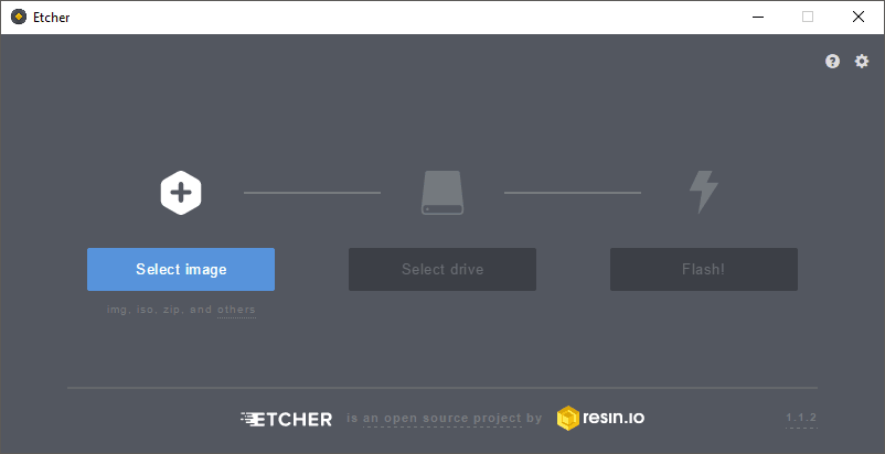
To flash the OS onto the SD card, follow these steps.
Insert the micro SD card into the card reader and verify that your computer recognizes it.
Click “Select image” button and find the Raspberry Pi OS Lite zip file that you downloaded.
Click the “Select drive” button and specify the memory card as the target location.
Click the “Flash!” button to write the image to the memory card.
Configuring Network
After Etcher is finished writing we need to configure the network for the Pi to connect to. These instructions are for the Raspberry Pi 3, which has built in Wi-Fi capabilities.
If you have an earlier version that does not come with Wi-Fi you will need a mouse, keyboard and monitor. Once obtaining these items connect them to the USB and HDMI ports. A command line terminal will appear on your monitor when loaded. You can now skip to the Installing NodeJs section.
If you have a Pi that comes with Wi-Fi you can configure your Pi to automatically connect to your Wi-Fi network on first boot. You will need to define a wpa_supplicant.conf file for your particular wireless network. Put this file in root of the sd card, and when the Pi first boots, it will copy that file into the correct location in the Linux root file system and use those settings to start up wireless networking.
After Etcher completes it typically unmounts the sd card, so you may need to unplug it and plug the card in again.
Copy the wpa_supplicant.conf example file below and add your ssid and password.
ctrl_interface=DIR=/var/run/wpa_supplicant GROUP=netdev
update_config=1
country=US

network={
 ssid="<Name of your wireless LAN>"
 psk="<Password for your wireless LAN>"
}
source: Setting up a Raspberry Pi headless
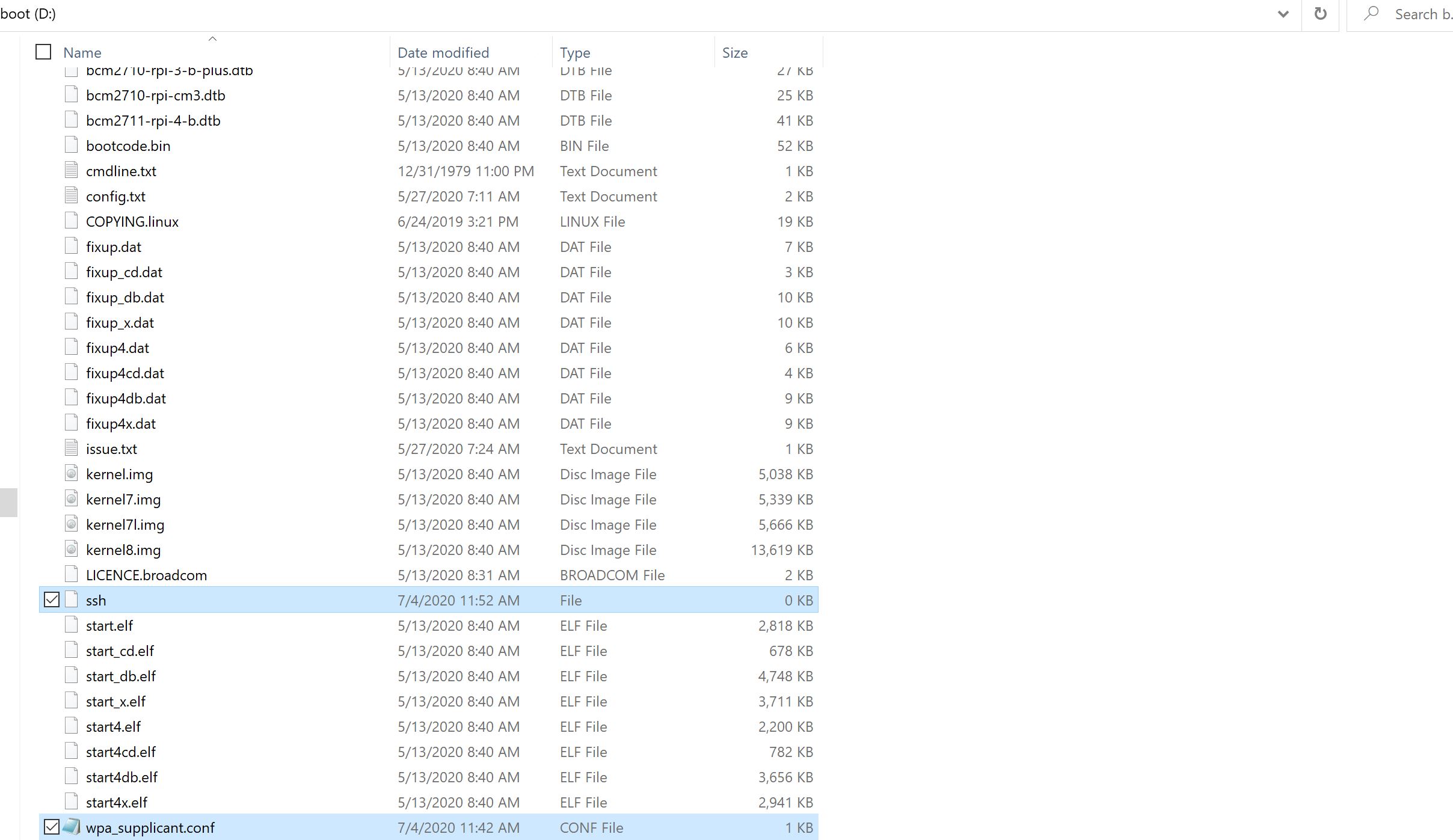
To enable ssh access on boot an empty ssh file should be created at the root of the boot sd card.
After adding the files the directory should look similar to the following.
Now remove the micro sd card and connect it to your raspberry pi. Give it a few minutes to configure. Now we will need to open up a terminal to test our connection to the Pi. This must be done from a computer connected to the same Wi-Fi network as the Pi. To open up a terminal in Windows we can use cmd which can be opened by entering “cmd” into the home search bar. If on Mac open up the search bar and search for “terminal”.
Run the following command from terminal to test your connection with the Pi. Please note that this will not work on UF’s Wi-Fi, you may need to use a phone hotspot for this to work.
$ ping raspberrypi.local
If connected correctly you should get several replies from the Pi. If not connected then you may get an error similar to Ping request could not find host raspberrypi.local. Please check the name and try again. This could mean that the Pi is still configuring the as it is the first boot, the Wi-Fi is not configured correctly, mDNS is not working correctly on your device. If you have access to the router the Pi is connected to confirm that it is connected from the router’s setting page. On the setting page of your router, there should be a list of devices and your raspberry pi should be listed there with an ip address.
If it is not listed, please verify the ssid & password configured in the wpa_supplicant.conf.
If it is listed and you still can’t ping it attend to ping it’s ip address directly (ie ping 192.168.0.1).
If you still can not connect, I would suggest getting a mouse, keyboard and monitor to continue manually.
The next step is to ssh into the device. To do so simply run the following command.
$ ssh [email protected]
OR
$ ssh pi@${IP_ADDRESS} # Replace with ip address of pi
After doing so you will be prompted to enter a password to enter, the default password is raspberry. After entering you should see an empty command line terminal.
pi@raspberrypi: ~ $
Installing NodeJs
Next thing to do is to install NodeJs as it is required for this repository. To start off run this command:
pi@raspberrypi: ~ $ sudo apt update
Now we need to pull in the node package.
pi@raspberrypi: ~ $ curl -sL https://deb.nodesource.com/setup_18.x | sudo -E bash -
Next install node.
pi@raspberrypi: ~ $ sudo apt-get install -y nodejs
Now to verify that node is installed correctly run this command:
pi@raspberrypi: ~ $ node -v
Clone Repository
Raspberry Pi OS does not come with Git preinstalled, so we must install Git to continue.
pi@raspberrypi: ~ $ sudo apt install git
Now clone the telemetry collector repository.
pi@raspberrypi: ~ $ git clone https://github.com/Solar-Gators/Sunrider-Firmware
Install pm2 (we’ll need this later).
pi@raspberrypi: ~ $ npm install -g pm2
Install the python dependencies with the following command:
pi@raspberrypi: ~ $ apt-get -y install python3 && \
                    apt-get -y install python3-pip && \
                    apt-get -y install python3-dev && \
                    apt-get -y install build-essential
Then install the pip dependencies:
pi@raspberrypi: ~ $ cd Sunrider-Firmware/telemetry-collector
pi@raspberrypi: ~ $ pip install -r requirements.txt
Now run the following command to build the software:
pi@raspberrypi: ~ $ make all
Ensure that it builds successfully.
Configuring UART
The RFD900x comes with a usb connection that can be connected to any of the raspberry pi’s UART ports. You will need to determine the device port and update the ecosystem.config.js file’s UART_PORT environment variable.
The quickest way to determine the port is by disconnecting the USB, run the following command, then reconnecting usb, run the command again, and see which port gets added to the list.
pi@raspberrypi: ~ python -m serial.tools.list_ports
Starting the Telemetry Collector
Start the collector using pm2:
pi@raspberrypi: ~ pm2 start ecosystem.config.js
Ensure the collector is online:
pi@raspberrypi: ~ pm2 ls
Save the collector so it can be easily started at boot up:
pi@raspberrypi: ~ pm2 save
When the pi starts the collector can be easily started with the following command:
pi@raspberrypi: ~ pm2 resurrect
Emulation
We have built an emulation library for emulating transmissions using the DAD board. See Testing
RF900x Raspberry Shield
A raspberry pi shield has been designed for the raspberry pi.
TO DO:
Assembly Guide
Usage Guide