Car Software
The code for this team is located in the Telemetry_2019-2020 repository.
Getting Started
First install the STM32CubeIDE as that is what we will be using for our toolchain and to program our boards.
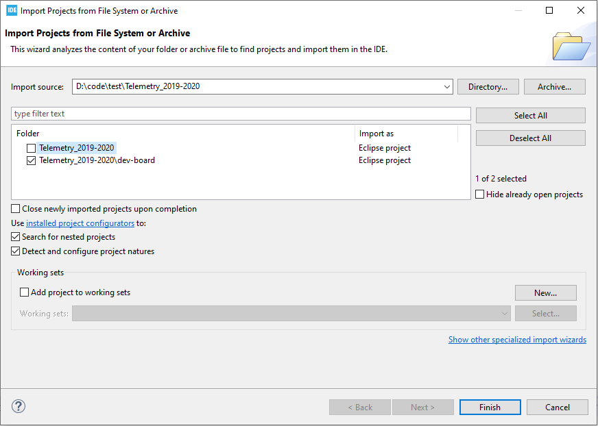
Next, clone our repository. Open the STM32CubeIDE on your computer and navigate to File->Open Projects from File System…. Browse by Directory to the “Telemetry_2019-2020” cloned directory and select it. Then as in the Figure below, only select the “Telemetry_2019-2020\dev-board” folder to import as an Eclipse project and select Finish. Now the project should be imported and you can see it on the Project Explorer pane to your left. If you are familiar with Eclipse, this IDE behaves very similar.
Building and Running The Code
To build this project, simply open up any file from this project in the IDE and select the build icon in the top toolbar. This compiles all the code and should succeed if nothing has been changed within the project.
In order to actually run the code on a microcontroller. Plug in either the development board for the stm32f072rb or a programmer hooked up to the stm32f072rb. If you are using a ST-LINK programmer proceed to the next paragraph, otherwise keep reading. If you are using the SEGGER-J-LINK programmer you need to access the Debug Configurations menu which can be found by clicking the dropdown arrow attached to the debug icon in the top toolbar. Once in the Debug Configurations menu, you must select select the “telemetry-dev-board.elf” file from the left hand pane. Then, click the Debugger tab at the top and change the Debug Probe to “SEGGER-J-LINK” and click Apply.
Now that the correct programmer has been selecting and hooked up to the computer and microcontroller, we can load the code on to the microcontroller by simply clicking the debug icon in the top toolbar.
File Structure
dev-board Folder
This folder holds all the source code for the project for the Telemetry board from 2019-2020. There are also several drivers that were created and can be found in the nested directories in the Src folder. Examples of how to use all of the drivers can be found in ‘Src/main.cpp’
CAN Driver
This can be found in the ‘subsystem-can-driver’ which contains all of the header files for the CAN API. An example of how to use the CAN-driver can be found in ‘Src/main.cpp’ and documentation for all of the functions can be found in their respective header files. Important: no external code is needed in order to get the CAN driver to run, the CAN driver handles all of the CAN peripheral initialization and interrupt handling that would normally be found in ‘main.cpp’, ‘stm32f0xx_hal_msp.c’, and ‘stm32f0xx_it.c’. Therfore delete any code related to CAN in these files.
Importing the CAN Driver to your STM32 project
Copy the ‘subsystem-can-driver’ folder into your project
Add the ‘subsystem-can-driver’ folder to your include path in your IDE for your g++ compiler.
If you are using STM32CUBEIDE to generate your code, then either make sure CAN is initialized in the .ioc and you will have to repeat step 6 every time you generate new code, or you will need to repeat steps 4-6 every time you generate new code.
If your project is not already using CAN, copy ‘stm32f0xx_hal_can.h’ and ‘stm32f0xx_hal_can.c’ from ‘dev-board/Drivers/STM32F0xx_HAL_Driver’ Inc and Src directories respectively.
Now in ‘dev-board/Inc/stm32f0xx_hal_conf.h’ uncomment “#define HAL_CAN_MODULE_ENABLED”.
Delete all CAN initialization/interrupt code from ‘main.cpp’, ‘stm32f0xx_hal_msp.c’, and ‘stm32f0xx_it.c’
You are now ready to start using this library!
RF Driver
This is a driver for the RFD900x board from RFDesign. The API for this driver can be found in the ‘transport-layer.h’ for initalizing and sending out RF packets and ‘rf-message-helper.h’ for adding messages to the RF packet before sending it.
GPS Driver
This is a simple driver for the Ultimate GPS Breakout from Adafruit that initializes and starts reception before checking if data is available and then getting the latest data. This driver utilizes a FIFO, so that more than one packet can be received at once.
IMU Driver
This is another simple driver used to interface with the bno055 IMU. All API documentation can be found in ‘bno055.h’. This header also includes all initialization for the I2C peripheral which it uses inside of the source file, therefore no other initialization should be done for this I2C peripheral outside the library.
templates Folder
This folder holds templates for all C and C++ header and source files that should be used when developing for this project. These templates contain commenting styles as well as example comments.