Startup Board
As previously discussed, the BMS, whether the Orion BMS or an eventual custom BMS we may eventually build, is responsible for taking various inputs from our battery pack, and converting those into signals we can use to determine whether it’s safe to start the vehicle. The startup board uses the Discharge Enable (DE), Multipurpose Enable (ME), Charge Enable (CE), and Charge Safety Enable (CSE), as well as 12 Main (12M_L, active low signal) and 12 Trip (12T), which don’t come from the BMS. To get a better picture of how the BMS operates, refer to the Orion BMS section. To gain an understanding of the other signals Startup doesn’t use, refer to the Orion BMS Wiring manual provided on that page.
The BMS Signals
The four signals provided by the BMS may be self-explanatory, but it’s important to have a solid understanding of what they mean. The BMS signals are all open-drain, meaning when true the signal sinks current to ground when false, has high impedance. DE is an open-drain signal that pulls down to ground when the battery is able to be discharged. The ME does the same thing, though the Orion can be programmed to turn this signal on based on other user-defined criteria. The two charge signals are used to determine whether it’s safe to charge, and the startupt board will connect the solar array’s MPPT to the battery pack if they’re both true. CE and CSE are again an open drain output, and CE is true when the batteries are adequately balanced, not full, and not too hot. The CSE signal is a little less useful for our application, though similar to the ME, we use the CSE as a backup signal to stop vehicle charging should conditions be inadequate. In many traditional electric vehicle applications, the vehicle can get charge through two sources, either a wall outlet or regenerative braking. CSE is primarily meant to allow the BMS to shut off wall outlet charging should the analog on/off switch fail.
The Other Signals
In addition to the 4 BMS sourced signals, there’s also 12 Main and 12 Trip. 12 Trip represents the supplemental power supplied by a small lead acid battery that allows the vehicle to always be connected to some sort of power. 12 Main represents the main power coming from the battery pack, and this signal is high when the battery is connected to the vehicle.
Startup Circuit
Startup Circuit Explained
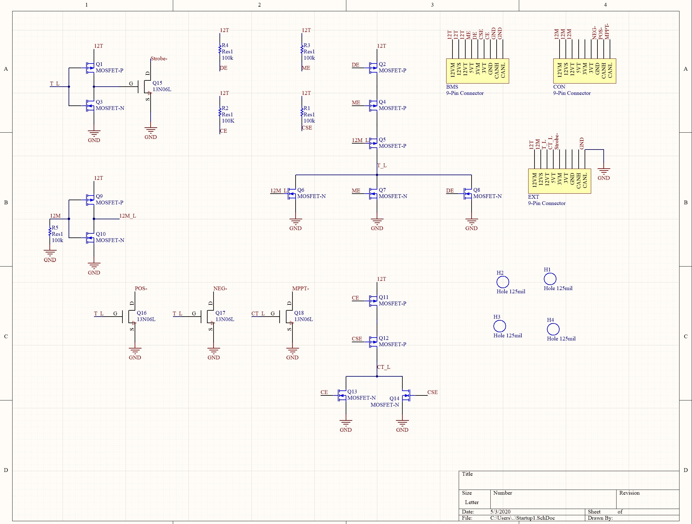
The startup circuit (sometimes referred to as trip circuit) is meant to use digital logic to convert the signals discussed earlier in the introduction, to two active low signals, Trip and CTrip. Active low means that the signal is true when the signal is 0, or low. As discussed in the BMS section, when it is determined that it’s safe to start the vehicle, both ME and DE will be active, and will sink current. At this point, the driver may press a startup button that will connect 12M to 12T temporarily, which finally makes all three signals active, and makes Trip active. Trip going active causes the contactors to close, connecting power to the vehicle, and now 12M is sourced from the main pack. Our Trip signal also controls a strobe light, because, as the name implies, this signal represents the car having tripped in some way. The way the current startup board is designed, this means that until the start button is pressed, the strobe will appear to indicate that the car is in unsafe conditions and in a trip state, when this may not be the case. However, this design is necessary, as it allows the driver to push a ‘kill-switch’ if they think something is wrong, and prevents the car from immediately restarting unless the driver pushes the start button. The CTrip side of things functions similarly, just a little less complicated as it uses 2 signals instead of 3. When CE and CSE are true, it will send CTrip low, allowing us to close the contactors connecting the MPPT to the battery pack.