Fluid Dyanmics
Fluid dynamics is the study that describes the way fluids flow, with many different subsections based on the type of fluid studied. For our applications, we are primarily concerned with the study of airflow, better known as aerodynamics. Our primary purpose for aerodynamics is to reduce drag - the atmosphere’s resistance on our vehicle as it attempts to move through the atmosphere. Understanding the principles found here will help you create a body with minimal drag, thus increasing its overall performance.
Drag has everything to do with the shape of the object you are moving. If an object has sharp corners and abrupt stops, air will resist its motion more than an object that is streamlined. Rounded corners and smooth surfaces permit air to flow easily across a surface as air particles do not have to change direction as rapidly. Consider for instance an airfoil. The front of an airfoil is rounded out so that air may easily cross onto its surface. Then, as air continues to move across the structure, there is a smooth surface which gently curves, letting the air meet back together at the tail.
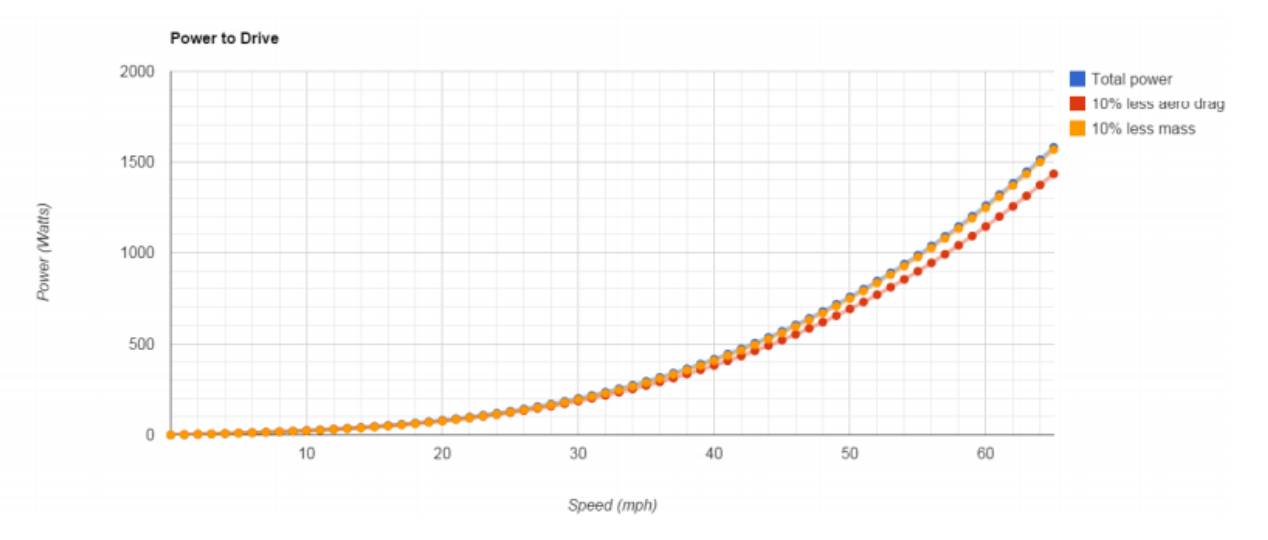
Drag is a key source of power draw, alongside rolling resistance. However, drag is a function of velocity squared, whereas rolling resistance is only a function of velocity, so the effects of increased aerodynamic are much more valuable (Fig. 1).
Considering the airfoil example and applying it to the car design process, we can see that there are multiple factors affecting drag. Separating these out, we can consider four primary components of the drag:
Pressure Drag is that resulting from the recombination of airflow across a body. In the airfoil example, it is mentioned that the surface gently curves to let the air meet back together at the tail. This feature of an airfoil is there to reduce this pressure drag. By creating a structure that guides the air back together smoothly, we limit the amount of separation following this stream. Creating small degrees where air flows back together like the tail of an airfoil is best. Additionally, if a surface curves too rapidly we observe stagnation points where air must change direction by right angles. Since the force of the car pushing air is perpendicular at this point, air is pushed forward rather than out of the way creating pressure. The front nose of the car and the front of the canopy are both locations where this is observed. And since this drag comprises 50-90% of all drag on solar cars, minimizing this component is greatly desirable.
Viscous Drag results from the airflow coming off of the airfoil. Since our airfoil example is smooth and curves gently, air flows over the surface gently and sticks to this surface. Air is a viscous fluid however. Air will naturally stick to the airfoil, consuming energy whenever it is pulled off. In terms of our car design, viscous drag represents a noticeable percentage of drag on the vehicle. Reducing this drag component is also of interest.
Induced Drag is the more complex principle concerning the reaction force responsible for lift. In the airfoil example, if lift is produced, a drag force will incidently be caused. In solar cars, we want to create as little lift as possible such that the remaining design can overlook this component. If lift were to be created, the addition of winglets on the vehicle may be necessary.
Interference Drag is created at any point where two sections of a body join together. Gaps, holes, outward features, and similar components will all introduce this form of drag. Since the airfoil is one continuous surface, very little interference drag will occur. Smoothing over the car body where possible and creating parts with close gaps is the best way to limit this force. This will help decrease incident effects on the boundary layer. On a further note, a design concept used on our previous car bodies is a lip around corner edges, such as where the canopy joins to the top of the car. The larger the radius of these lips, the less interference drag (and in the case of the canopy, the less pressure drag) we observe. However, we have typically used a 45mm fillet when possible. This size represents both a reasonable radii to be used in this application and positive effects on drag.
And on that, we need to establish what a boundary layer is. This concept can be described as the thin layer of air that flows across any body on the surface (or, at the boundary!). By reducing these drag factors above, we also positively impact the boundary layer by creating a laminar flow - flow where air does not break apart. In places where laminar flow is not maintained, turbulent flow will take its place. As its name suggests, this flow has very little stability, causing vortexes along the surface. With these present, the car needs to exert more power to break their effect, thus consuming more precious energy.
A general topic that concerns pressure, viscous, and interference drag is where to place the car’s canopy. For practicality, the canopy should be somewhere that can fit a person safely (of course!). Placing it too far forward will create a wake on the top surface of the car, increasing interference drag. Placing it near to the center of the vehicle may be a good idea, but airflow may need to be redirected around a right angle, creating a pressure drag. And no matter where you place it, the air will stick to the surface creating viscous drag. This is a balancing act which your concepts will need to account for.
The key takeaways from this section should be how the different types of drag are created. By understanding how these forces occur and by analysing how we and other teams have worked around them in the past, we can create a car designed for the highest efficiency possible.